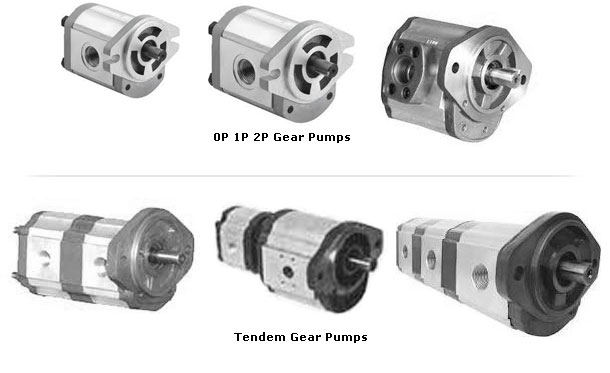
Basic Range
Gear Pumps are available for industrial use in different size flow of 0.8 lpm to 6.8lpm & 7.7 lpm to 40.00 lpm and upto 225lpm @ 1500 rpm. also make multiple pump and special pumps as per customers requirements.
Efficient Hydraulic Gear Pumps
High quality of gears to minimize leakage across gear tips, high precise geometrical tolerance of body and bearing blocks with seals for high volumetric efficiency and specially designed thrust bearing / bush gives low noise, Du-lined /bi-metal bearings for jerk less operation and working against high mechanical loads operating up to 200 bar and up to 3000 rpm.
Low pressure bearing lubrication is feature of all Gear Pumps, this is achieved by utilizing the action generated when the gear teeth separate to draw lubricating fluid from the inlet port and along each bearing journal by way of passage in the composite bush. This proven system ensures efficient cooling and lubrication of the bearing with a constant supply of fluid independent of operating condition.
DURABILITY
All Gear Pumps are backed by full 3 months warranty. High tensile aluminum alloy are used to ensure maximum fatigue strength. Through body bores enable precise alignment of the bearing and hence maximum s bearing load capacity. Careful attention to machining details and surface finishes, holds wear rates to a minimum and promotes extended operating life. Gear Pumps have been designed to perform with a wide range of fluids and can be supplied with nit rile and piton seals as required.
DRIVES
Use of a flexible coupling is recommended to accommodate any slight misalignment of shaft and to dampen vibration. Splines must allow sufficient radial movement. Two couplings are necessary to ensure radial alignment. Both parallel and taper shaft units are supplied with a shaft key, the parallel shaft keys must be hand fitted when the coupling is assembled. On no account must the key of coupling be fitted, or removed by hammering or levering, this will damage the pump internally.
MOUNTING
The pump may be mounted in any position. The units are supplied with either two or four bolt flanges and with a spigot for location. The fixture that receives the mounting flange spigot should have 1 mm 45° chamfer to ensure proper installation. To minimize vibration, which can be transmitted to the pump by rigid runs, it is good practice to use flexible hose immediately connected to the unit ports.
ROTATION
Inlet and rotation arrows are stamped on the unit body, adjacent to drive shaft rotation.
PUMP SUCTION LINE
The suction line must be as large as possible and should be free from sharp bands to prevent excessive suction head, which should in no case exceed 190mm of mercury (0.24bar) below atmospheric pressures. The system should be designed to prevent entry of air and a positive head of oil should be maintained wherever possible. Lower pressure during cold start up conditions are permissible for short periods. As a general guide, fluid velocity in the pump suction line should not exceed 2 m/sec. for pipe lengths up to 2 meters.
OIL RESERVOIR
As a general, the reservoir capacity for industrial applications should be three to five times the open loop flow per minute being drawn from the reservoir. For mobile applications the reservoir should be sized for not less than 0.75 times the open loop flow (of course, the volume for rams and actuators must be allowed for providing adequate air space and breathing.) The pump suction line should draw oil from a point not less than 100mm above the tank bottom to avoid sludge deposits from entering the pump. The return line should be submerged to limit frothing of oil. The suction and return connections should be positioned s far apart as possible and separated by baffles, so that oil circulations promoted within the tank to assist convection cooling and allow air entrained in the oil dissipate.
FILTRATION
The fluid should be filtered during top-up and continuously during operation to achieve and maintain a cleanliness level of ISO 17~/14. The recommendation should be considered a minimum. Better Cleanliness levels will significantly increase component life. Each systems should be analyzed to determine the proper method of filtration needed to maintain the required cleanliness levels. depending on the configuration and complexity of the system.
FLUIDS
Most premium grade mineral oil based hydraulic fluids are suitable for use with Gear Pumps. A primary consideration in the selection of Hydraulic fluid is expected oil temperature extremes that will be experienced in service. When choosing the Hydraulic fluid, these temperature extremes must be considered to obtain the most suitable temperature-viscosity characteristic. For optimum performance, the viscosity should be maintained in the 97-456SUS ( 20 – 100 – cST) Cange. Limiting viscocities of 4545 SUS (1000 cST) maximum and 52 SUS ( 8 cST) minimum should not be exceeded. It may be possible in some application to run on other types of special fluids contact WELEX for more details.
OPERATING TEMPERATURE RANGE
The pumps are designed to operate between 0° and 80° C intermittent temperatures may vary between -20° to 100° C if the fluid being pumped is suitable for such operations.


